The collector currents I1 and I2 from Q1 and Q2 flows in the same direction through the corresponding halves of the primary of the transformer T2. This condition is reversed when the negative half cycle is applied to the transistors. The other transistor stays reverse biased during the positive half cycle. One transistor gets forward biased during the positive half-cycle and passes the current. The input coupling transformer T1 divides the input signal into two identical halves, every 180 degrees out of phase. It contains two anti-phased transistors Q1 and Q2. The output stage of this amplifier can drive the current in both directions through the load. Thus, the cross over distortion is reduced in the Class AB amplifier. This arrangement reduces the time during which the transistors will be simultaneously OFF. But unlike Class A in Class AB biasing resistor values are selected such that the transistors Q1 and Q2 are biased just above the cut in voltages. This circuit is similar to the Class A Push-pull amplifier. Thus, the efficiency of the class B Push-pull amplifier is higher than the Class-A Push-pull amplifier.Ĭircuit Diagram of Class AB Push-pull Amplifier The transistors do not consume any power during the ideal conditions. Here the two transistors are biased at the cut-off points. There are no biasing resistors R1 and R2 in the Class-B amplifier.

Circuit Diagram for Class B Push-pull Amplifier This cancels out the magnetic saturation in the circuit. The quiescent current from Q1 and Q2 flows in the opposite direction through the halves of the primary of T2. The load is attached to the secondary of the transformer T2. The power supply is connected between the center tap of the primary of T2 and the emitter junction of the Q1, Q2. The base ends of these two transistors are connected to the secondary winding of the input transformer T1. The collector terminals of these two transistors are connected to the two ends of the primary winding of the output transformer T2. One transistor has to be forward-biased during the positive half-cycle of the signal while the other during negative half-cycle. Resistors R1 and R2 are used for biasing the transistors. The emitter terminals of these two transistors are connected together. The Class-A amplifier contains two identical transistors Q1 and Q2. Circuit Diagram for Class-A Push-pull Amplifier The circuits designed for these classes are different. This amplifier can be constructed in different configurations such as Class-A, Class-B, and Class-AB Push-pull amplifiers. To divide the input signal into two identical signals 180 degrees out of phase, a center-tapped coupling transformer T1 is used at the source of the amplifier. One transistor gets forward biased during the positive half cycle of the signal while the other during the negative half of the cycle. PullTube requires OS X 10.11 or higher.The circuit of the Push-pull amplifier contains two transistors, an NPN and a PNP transistor, as active devices.

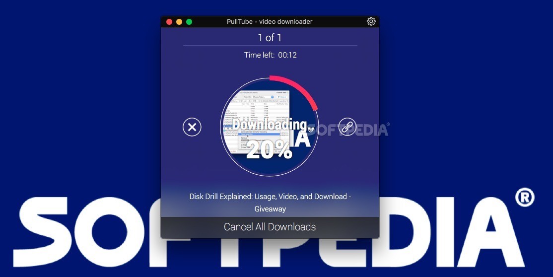
If PullTube notices video to be part of some playlist, it will suggest you to download that playlist as well. The app will fetch data for it and you just select the desired resolution or audio format.


PullTube offers you the possibility to download videos from both sources (YouTube and Vimeo), while other platforms might be added at a later time. SeptemVideo Last Updated on Septemby admin. PullTube – Online Video Downloader 1.5.4. Convert Vimeo, Youtube videos to MP4 or just save audio to MP3 and M4A. PullTube A beautiful online video downloader for your Mac PullTube proposes a streamlined workflow for quickly downloading videos from. PullTube Video Downloader 1.0.2 ★★★★★ DOWNLOAD.


 0 kommentar(er)
